
Harmonics Don’t Exist – and How We Measure Them
In the world of power quality there is one topic that constantly captures the imagination of electrical engineers: harmonics. In today’s power system, where electrical loads are increasingly complex and evolving, so too are the concepts that surround harmonics. We are seeing the introduction of terms such as inter‑harmonics and, more recently, supra‑harmonics. Each new term bringing with it new questions about measurement, regulation, and the impact on the grid.
The Traditional Concept of Harmonics
You can consider that harmonics don’t actually exist. One of the favourite things a mentor of mine said to me about power quality is something I still like to use when talking about the subject today: “Harmonics don’t exist; they are a mathematical calculation used to explain the distortion of a waveform.” That is a very simplistic way of looking at the concept, but it also captures why we are so interested in the topic of “harmonics” because these unknown frequencies can have an impact on the day to day electrical measurements we make.
In their simplest form, harmonics are sinusoidal components whose frequencies are an integer multiple of the fundamental supply frequency (typically the 50Hz we have in the UK and Europe). The EN 61000‑4‑7 standard defines how to test and measure the harmonics, and where we see the basic idea that the waveform we are measuring is a repeatable signal over the duration of the measurement window. This sampling window is 200ms which for a 50 Hz supply allows us to capture exactly ten full cycles (20 ms each). This is enough data to use to start making the calculations needed for our power quality measurements.
Sampling and Aliasing
A critical point in any harmonic analysis is the sampling rate. Because an analog‑to‑digital converter (ADC) can only capture frequencies up to half its sampling frequency (the Nyquist limit), we must sample at a frequency of at least twice the highest harmonic we want to measure.
| Harmonic | Frequency (Hz) | Minimum Sampling Rate (Hz) |
|---|---|---|
| 1st (fundamental) | 50 | 100 |
| 50th | 2500 | 5000 |
| 100th | 5000 | 10000 |
Most modern power quality analysers that comply with the EN61000‑4‑30 standard will sample well above the minimum requirement (usually ≥ 10 kHz). This will give us more than 200 samples per cycle that can then be used for the Fast Fourier Transform (FFT) used to calculate the harmonic content of the signal.
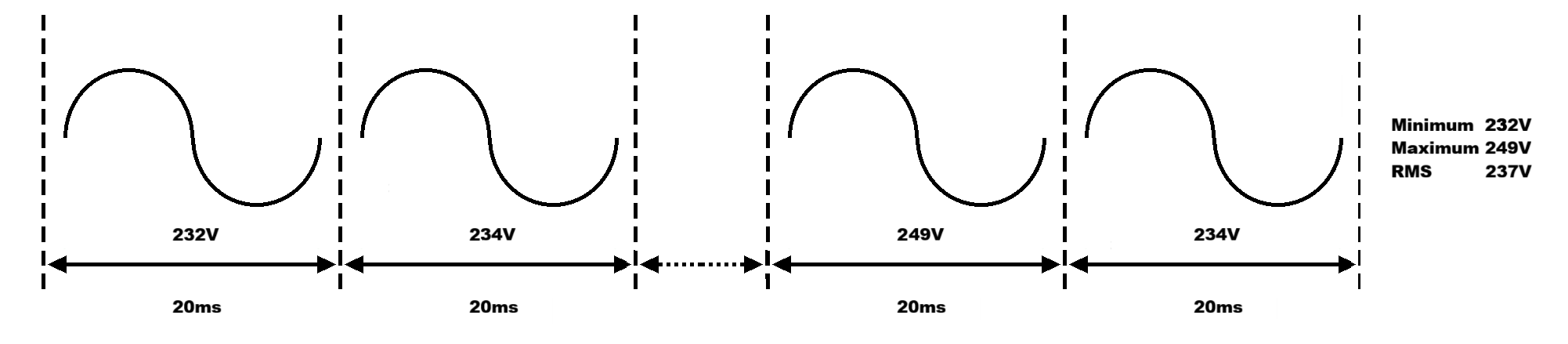
200ms sampling window: Ten cycles of samples taken by the meter will produce RMS values for the fundamental,
each harmonic and total harmonic distortion (THD).
The FFT process of transforming these samples produces the “harmonics” that we have all read about in technical literature: the 3rd harmonic (150 Hz), the 5th harmonic (250 Hz), and so on, all the way up to the 40th, 50th or in certain situations higher order harmonics up to the 100th harmonic may also be considered.
Inter-harmonics
We have defined harmonics as integer multiples of the fundamental, however in the real world, the samples we make of our loads are not perfectly repeatable over our 200ms sample window and synchronised to our fundamental frequency of 50Hz. Because of this we can then introduce the concept of inter‑harmonics. With these harmonics we are referring to the frequency components that are represented as smaller integer steps between two adjacent traditional harmonic orders.
Why Inter-harmonics Exist
The idea that we have a repeatable signal is there to make the method used for our harmonic calculations easier for the meter to process. In reality, variable speed drives, LED lighting, UPS units and other power electronics devices can introduce frequency components that are influenced by other events, such as fault transients, and therefore will not be a repeatable signal in our 200ms sampling window.
For example, a three phase induction motor operating under a variable supply frequency can produce an inter‑harmonic at 50Hz plus the motor’s mechanical frequency. Or we may have a switched mode power supply that might produce a ripple around 400Hz which is not an integer multiple of 50Hz.
Grouping Inter‑harmonics
Because inter‑harmonics are usually at a lower magnitude than our main harmonic frequencies, they are often grouped together to provide a more meaningful measurement indication. One common approach is to create an inter‑harmonic group that encompasses the frequency band between two adjacent harmonic orders. The group is represented by a single value that reflects the total distortion within that band.
Another method used is to find the main harmonic orders and then calculate the frequencies between them to produce a combined harmonic group RMS value. This measurement can typically be seen in EMC (Electromagnetic Compatibility) compliance testing, where manufacturers need to demonstrate that their products do not exceed certain limits across a wide frequency range.
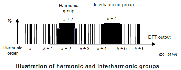
Diagram taken from EN61000-4-7: Testing and measurement techniques –
General guide on harmonics and inter-harmonics measurements and instrumentation.
At present, there are no defined limits for inter‑harmonics in standards like EN50160 which covers voltage characteristics, THD and harmonics up to the 25th order. Instead, our interest in any harmonic grouping may be down to what we are investigating and could differ when looking at a small commercial office as opposed to a larger installation such as a data centre where higher frequency distortion and the potential affect is maybe more of interest.
Supra‑harmonics
As the power industry moves toward converter based systems with devices such as electric vehicle (EV) chargers, renewable energy inverters and high speed DC‑DC converters, we are starting to see how supra‑harmonics are going to become more of an issue. Supra‑harmonics are frequency components above 2 kHz that have no relationship to the fundamental supply frequency and they can span from 2 kHz all the way up to 150 kHz (or even higher in some power electronics applications).
Why Supra‑harmonics Matter
Unlike traditional harmonics, supra‑harmonics are often the result of high frequency switching in power electronics. The presence of these components can:
- Induce additional heating in conductors and electronic components, shortening lifetimes.
- Generate audible interference (below 20 kHz) in sensitive environments.
- Trigger false operation of protection devices (relays, fuses) that are not designed to ignore high frequency noise.
- Interfere with mains signalling or power line communications (PLC), which operate in the 1–2 kHz range.
- Cause failure of cable terminations and connections in medium or high voltage installations due to dielectric breakdown.
- Disrupt device specific functions, such as the internal clocks in microcontrollers that can be affected by spikes at 77.5 kHz.
These effects show why supra‑harmonics cannot be ignored, even though they lie outside the traditional harmonic spectrum we currently look at.
Standards in Development
A standard that will address supra-harmonics is EN 50745 which is currently under development. It will cover emission limits for harmonics, inter‑harmonics, and supra‑harmonics below 9 kHz for low voltage installations. While EN 50745 will help set limits for devices and systems, further standards are needed for grid codes (EN50160) and for specific applications such as EV chargers.
Until such standards are fully adopted, manufacturers and DNOs must rely on best practice guidelines and in-field measurements. Modern power quality analysers are beginning to incorporate supra‑harmonic measurement capabilities, allowing engineers to evaluate the Total Supra‑harmonic Distortion (TSHD), similar to the traditional THD measurement.
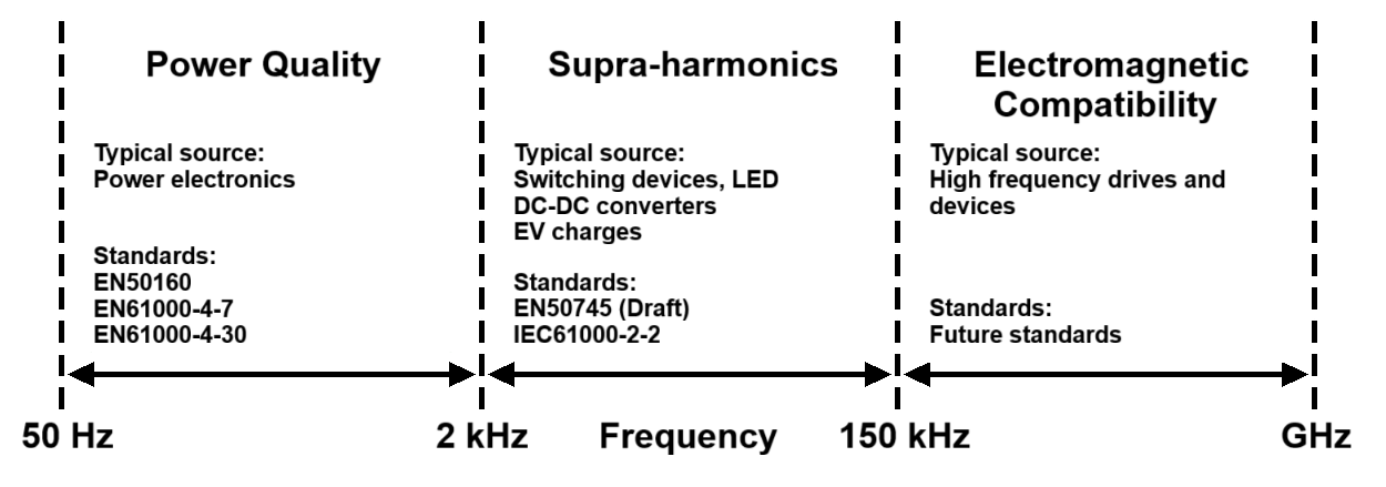
Harmonic frequency bandwidths and standards
The Future of Power Quality Measurement
The transition toward converter based power systems means that the definition of “harmonic” will continue to evolve. While the traditional harmonics (up to the 100th order) remain a regulated and well understood part of power quality, supra‑harmonics are, like transient events, still largely unregulated.
This creates a challenge for engineers who must develop new measurement techniques, tools, and mitigation methods for frequencies that were previously considered outside the scope of power quality analysis. But it also creates an opportunity for the same engineers to help set industry standards, shape future grid codes, and ensure the reliability of the next generation of power electronics devices.
Learn more about our products and services by visiting our Power Quality Expert product catalogue, Sonel product catalogue , Electrex product catalogue or Elspec product catalogue or you can contact us to discuss your measurement requirements further.
You can also follow Power Quality Expert on LinkedIn for regular news on products, events and technical updates.