
The Worlds 1st Ride Through Compliant SVC “kVAR Booster” Solution
Asynchronous generators, including doubly-fed rotors, are widely used in wind farms. During voltage drops, any slight speed deviation of these rotors consumes large amounts of reactive energy. Due to the large demand for reactive power during significant voltage drops, FRT regulations have been implemented in many modern grid codes.
A typical voltage drop event is the result of a short circuit on one of the network branches. It takes at least 100-200 ms to isolate the faulty substation, potentially deteriorating the voltage stability. The majority of modern grid standards require reactive energy to be generated by local networks during a fault.
The most reliable reactive energy solutions are based on capacitor banks, Static VAR Compensation (SVC). However, utilising a SVC as a ride-through solution has its disadvantages. The provided reactive current is proportional to the voltage, while the reactive power is proportional to the second power of the voltage (V²).
Fault Ride Through Solution
The Equalizer RT system is the Elspec Ride Through solution for asynchronous Turbine which is based on Elspec Real Time Static VAR Compensation technology which is used worldwide.
The Equalizer is a transient free static compensation system which has been modified in order to boost supplied kVAr capacity for short time voltage dips applications.
The Equalizer RT system is based on the following features
- Transient-free connection of capacitors
- Voltage Control operation mode – optimised to fulfil the Spanish PO12.3 Grid Code requirements.
- Ultra fast acquisition time – full compensation within less than 10mSec
PO12.3 Grid Code Compliance
The purpose of this code is to provide a procedure to ensure the uniformity of tests and simulations, the precision of measurements, and the assessment of the response of wind farms in the event of voltage dips.
Measurement Technique
The code requires that for all field tests, all of the records of voltage and current sampled for each phase must be carried out at a sampling frequency of 5 kHz minimum.
Voltage Dip Zone Classification
Note: T1-T4 are defined by the dip threshold (IEC 61000—4-30)
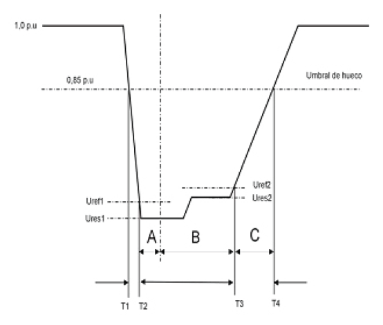
A, B, and C are used to define three zones during the voltage dip. These zones are classified as a function of the dip threshold and the residual voltage.
- Zone A: all of the values of voltage Uef (1/4) between T2 and T2 + 150 ms.
- Zone B: all of the values of voltage Uef (1/4) between T2 + 150 ms and T3.
- Zone C: all of the values of voltage Uef (1/4) between T3 and the lesser of the following values, T4 and T3 + 150ms
Methodology for Calculating Power
Power consumption is expressed in a normalised value (p.u.) to the registered nominal power of the Wind Turbine Generator tested. Similarly, energy consumption values are expressed in normalised values of power by time unit in milliseconds (ms p.u.)
The voltage and current levels registered in the test, as well as data obtained from simulations must be included in the report form as the table below.
| Three Phase Faults | OP 12.3 Requirements | Result |
| Zone A | ||
| Net consumption Q<15% Pn (20ms) | -0.15 p.u. | |
| Zone B | ||
| Net consumption Q<10% Pn (20ms) | -0.1 p.u. | |
| Net consumption Q<5% Pn (20ms) | -0.05 p.u. | |
| Average In/Itot | 0.9 p.u. | |
| Extended Zone C | ||
| Net consumption Ir < 1.5 In (20ms) | -1.5 p.u. |
The Fault Ride Through Test
The 1.5 MW turbine can be supplied with an automatic power factor correction system that makes it compliant with even very demanding grid codes; the turbine has ride- through capacity for all normal faults.
The Test Setup
The Real Time Controller (RTC) and the Equalizer RT containers were located in adjacent to the Turbine. The RTC container was connected to the medium voltage (20kV) in order to simulate voltage dips according to the Spanish Grid Code PO12.3.
A Elspec Equalizer RT system was connected at the turbine transformer output (690V). The Elspec Equalizer RT container was comprised of 4 x Elspec G4K BLACKBOX model EG4420. This meter is an advanced power analyzer which was used to carry out the measurements in the following network points:
- Grid input to the RTC container system 20kV.
- RTC container system output to the turbine: approximately 20% of the medium voltage (during the dips).
- Transformer output of the turbine – 690V (measurements of the turbines generator and the Equalizer RT system).
- Equalizer RT system output
The measurements were carried out continuously during the test period. All network parameters were recorded cycle by cycle at 1024 samples per cycle for voltages and 256 samples per cycle for currents.
Low Power Conditions
Low Power Test (10% – 30% of nominal)
The test comprises six tests as follows:
Three sequential unbalanced tests
Three sequential balanced tests
The following table provides the reactive current and energy values which were required from the Equalizer RT system in order to comply with PO12.3. The values were confirmed by a qualified company for the PO12.3 test procedure, which was carried out using a Ride Through test container.
| Zone | Reactive Current | Reactive Energy |
| A | Above 2000A | Above 800kVAr |
| B | Above 2000A | Above 800kVAr |
| C | 2000A to 3500A | 800 to 3300kVAr (*) |
(*)The value is changed in proportion to the voltage magnitude
Low Power Results
The effect of the Equalizer RT on the Grid at low power mode of operation of the turbine (<30%) is seen in Figure 4. It illustrates the consumption of the reactive energy and the current in MV at the connection point of the turbine to the Grid. It also provides the current waveform of the Equalizer RT in Low Voltage.

Without Equalizer RT, the consumption of reactive energy during Zone C almost reached 3 MVAR. With the Equalizer RT, it reduced to less than 500kVAR. In Zone A & B, the Equalizer RT contributes substantial reactive energy to the Grid (above 800kVAR).

High Power Conditions
High Power Test (more than 1300kW)
The test comprises the same set of parameters as the Low Power Test:
Three sequential unbalanced tests
Three sequential balanced tests
The following table provides the relative current values which were required from the Equalizer RT system in order to comply with the PO12.3. The values were confirmed by a qualified company for the PO12.3 algorithm.
|
Zone |
Reactive Current |
Reactive Energy |
|
A |
Above 3300A |
Above 1500kVAr |
|
B |
Above 3300A |
Above 1500kVAr |
|
C |
3500A-5500A |
1500-6500kVAr(*) |
(*)The value is changed in proportion to the voltage magnitude
High Power Results
The effect of the Equalizer RT on the Grid at high power mode of operation of the turbine (>1300kW) is seen in the graph, which illustrates the consumption of the reactive energy and the current in MV at the connection point of the turbine to the Grid. It also provides the active power of the turbine.

Without the Equalizer RT, the consumption of reactive energy during Zone C almost reached 7 MVAR. With the Equalizer RT, it reduced to almost zero. In Zone A & B, the Equalizer RT contributes substantial reactive energy to the Grid (above 1500kVAR).

To learn more please visit the Equalizer RT product page or contact us to discuss how we can help you with our Fault Ride Through power quality solutions.
Power Quality Expert
Learn more about our products and services by visiting our Power Quality Expert product catalogue, Sonel product catalogue , Electrex product catalogue or Elspec product catalogue or you can contact us to discuss your measurement requirements further.
You can also follow Power Quality Expert on LinkedIn for regular news on products, events and technical updates.