
Periodic inspection of a photovoltaic system after 5 years of operation
By performing a professional periodic inspection of a 5-year-old photovoltaic installation in accordance with the EN 62446-1 standard using a meter like the Sonel PVM-1021 meter and the Sonel IRM-1 means that the proper energy production can be assessed and any hidden faults can be detected.
Why is monitoring the inverter alone not enough?
The large number of photovoltaic systems now in use means that their subsequent operation and the maintenance to an adequate level of safety and efficiency is becoming increasingly important. While performing a full testing schedule during the commissioning of a new system is standard practice, in the subsequent years of operation, inspection is often reduced merely to monitoring the inverter operation and observing the energy produced.
However, it should be remembered that energy production does not always mean the installation is a good technical condition. Insulation degradation, damage to surge protection devices, or even the deterioration of the electrical connection quality can still remain undetected.
Inspection of a 5-year-old photovoltaic system in practice.
In this example, a PV system operating at a single-family home was inspected. The photovoltaic modules were mounted on a ground based structure, while the inverter was located at a distance of approximately 20–30 m from the PV generator.
The scope of the inspection and the tests applied during the verification of PV systems were in accordance with EN 62446-1.
These tests included:
- Visual inspection of the installation
- Open circuit voltage measurement (UOC)
- Short circuit current measurement (ISC)
- DC side insulation resistance measurement (RISO)
- Checking the continuity of protective conductors and equipotential bonding (RCONT)
- Recording of the environmental conditions
The photovoltaic meter used to perform the measurements was the Sonel PVM-1021, which was used along with the solar radiation and temperature meter Sonel IRM-1.
Stage 1 – The Visual Inspection and Identification of DC Circuit Parameters
The first stage of the inspection was a detailed visual verification of the installation. Based on the rating plate, LONGi LR4-66HPH-415M modules with a nominal power rating of 415W were identified.
The installation consisted of 22 modules divided into two strings of 11 modules connected in series. Each string was connected to the inverter via a separate pair of DC cables and these were tested individually.
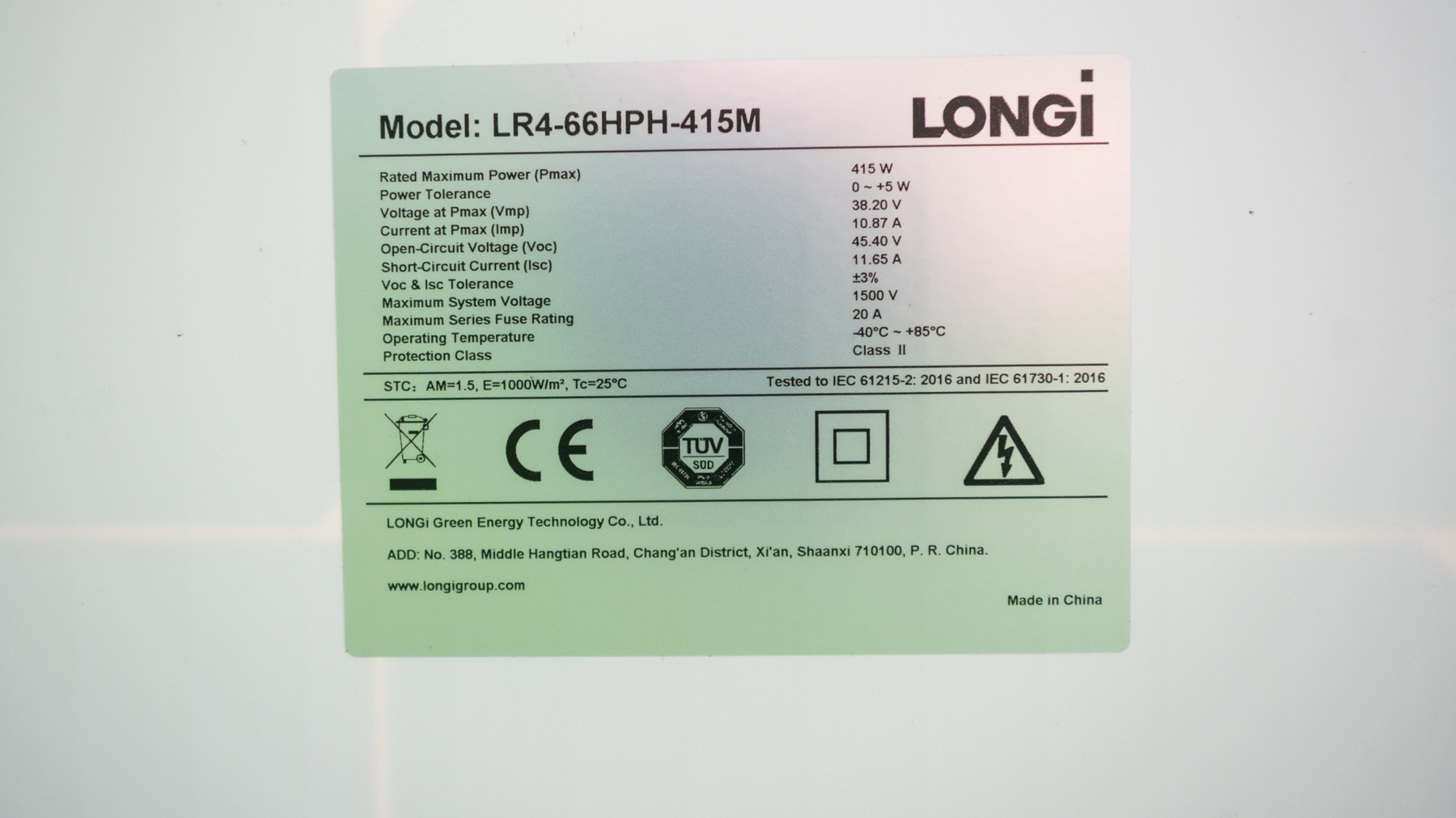
Module nameplate – reference point for string configuration and results
During the visual inspection the following were checked:
- Surface and frame condition of the modules
- Mounting of panels to the structure
- Cable routing underneath the modules
- Condition of visible connectors and junction boxes
- Cable protection against friction and sharp edges
- Equipotential bonding of the structure
- Markings and protective devices on the DC side
Visual inspection result: No mechanical damage to the modules or signs of overheating in the cables or connectors was found. The visual inspection of the AC distribution board also gave a positive result.
Stage 2 – The Measurement of protective conductors and equipotential bonding continuity (RCONT)
The next step was to measure the continuity of the protective conductors and the equipotential bonding. One measurement point was located at the PV installation and the second was in the area of the inverter and main equipotential bonding.
Due to the significant distance it was necessary to use a 30-meter test lead. Prior to the actual test an auto-nulling of the meter was performed. This is to compensation of the additional test lead resistance. The RCONT measurement was performed with the Sonel PVM-1021 meter at a test current of approximately 200 mA.
The obtained measurement results:
- PV frame connection continuity: 0.2 Ω
- Continuity of frame to inverter connection: approximately 0.6 Ω
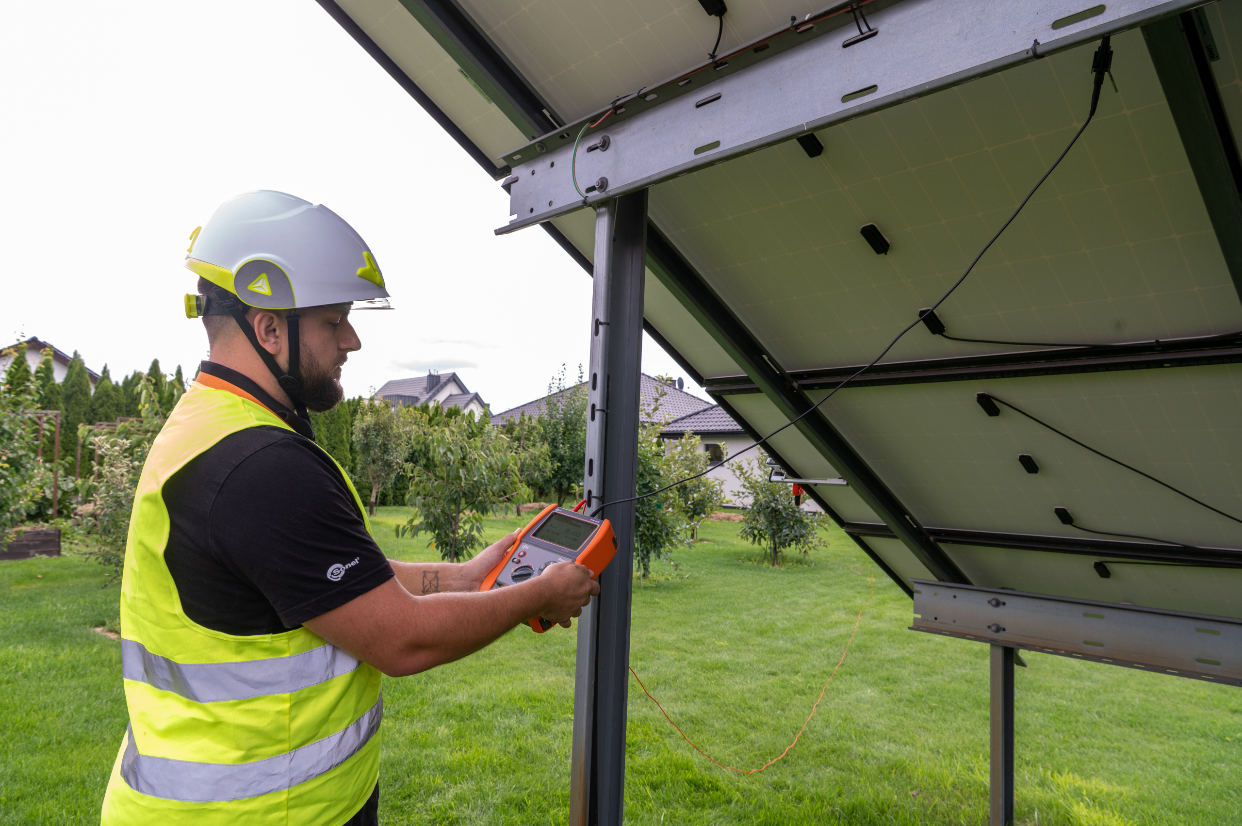
Continuity measurements with the PVM-1021 meter
A big advantage for a field technicians is the built-in AutoStart function in the Sonel PVM-1021. It will automatically initiate the measurement upon detecting the appropriate measurement conditions. This automatic test option is available where resistances are lower than 21 Ω.
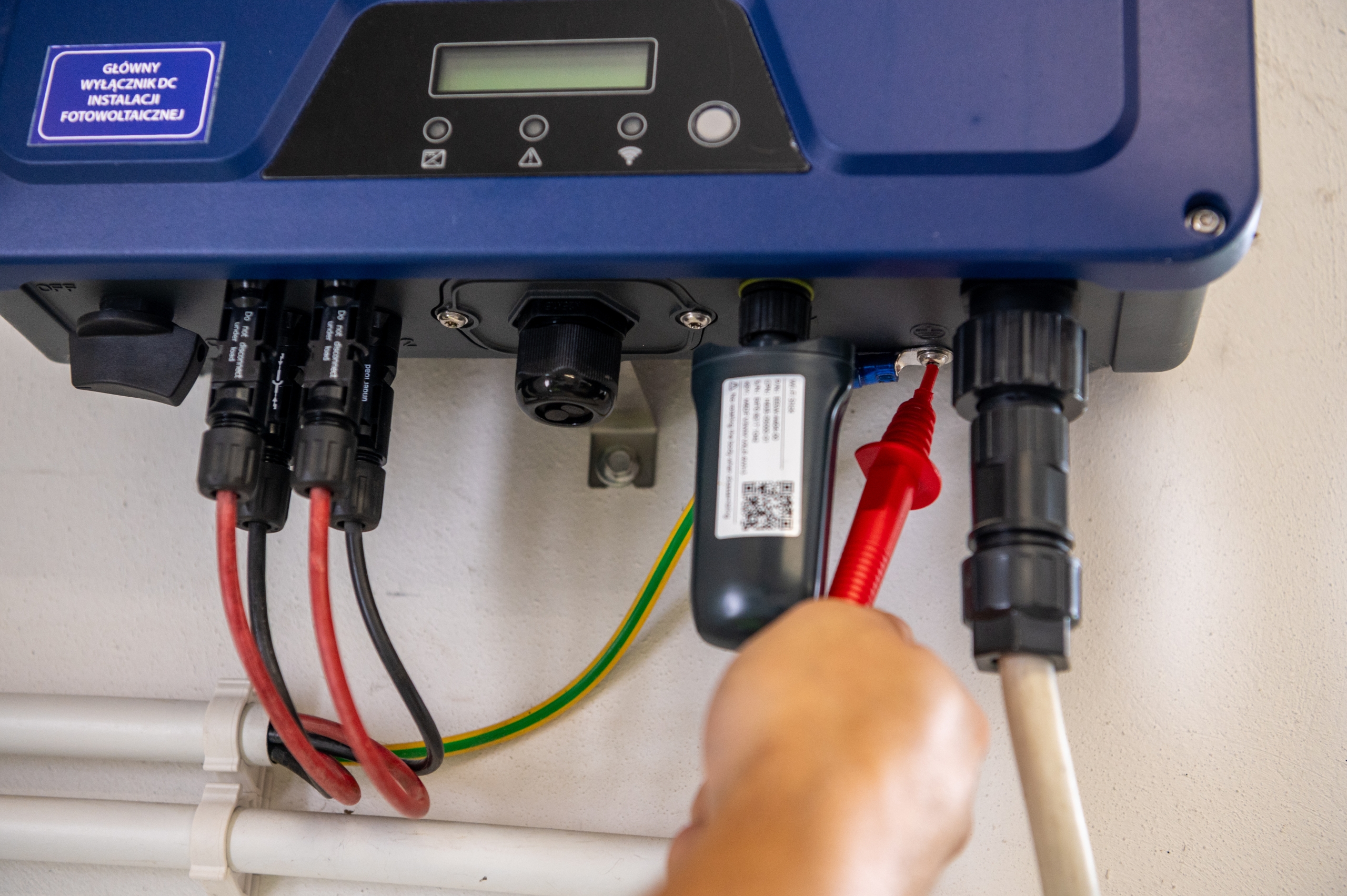
Meter connection during continuity measurement near the inverter
Stage 3 – Recording of the environmental parameters and STC conversion
The solar radiation and temperature is measured by the meter Sonel IRM-1. This was positioned in the same plane as the tested modules so that the irradiance sensor reflected the irradiation conditions of the tested. By use the IRM-1 with its mounting kit, the temperature probe enables the measurement of both the PV module and ambient temperatures.
The environmental parameters are used to convert the measurement results to STC conditions. These results are transmitted remotely to the Sonel PVM-1021 meter in real time via wireless LoRa® radio technology.
The status of the two meters connection is continuously indicated on the display of the Sonel PVM-1021 (a flashing icon indicates connection initiation, while steady light indicates established stable communication). During the connection, the PVM meter can continuously account for current irradiance and temperature to make instantaneous STC value calculations.
If radio connection between the two devices is temporarily interrupted, the IRM-1 uses a reSYNC function which automatically starts to save the environmental parameters into its local memory for transmission to the PVM once their connection is restored.
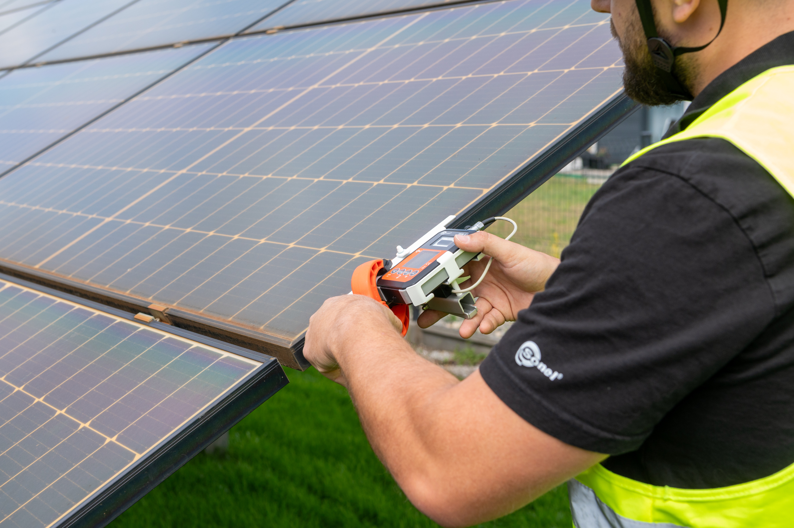
Sonel IRM-1 on the photovoltaic system structure
Stage 4 – The Core DC side measurements in AUTO mode
The key part of the inspection was performed in the AUTO mode. This mode allows the Sonel PVM-1021 to help automate part of the work of the site technician as the meter can automatically carry out a sequence of the three basic DC side tests.
After preparing the installation and disconnecting the tested string from the inverter, the Sonel PVM-1021 is connected via MC4 adapters to the positive and negative leads. The third lead is connected to the grounded mounting structure of the installation.
Before starting the measurement, the nominal parameters of the tested module/string and appropriate temperature coefficients α and β are then entered in accordance with the manufacturer’s documentation.
After setting the parameters and pressing the START button, the meter will automatically execute the following tests:
- Open circuit voltage measurement (UOC)
- Short circuit current measurement (ISC)
- Insulation resistance measurement (RISO+ and RISO-)
During this automatic sequence there is no need to switch the meter functions or reconnect test leads between each consecutive test. In practice, this means fewer operations performed by the operator, shorter working time at the string and lowering the risk of error when changing the measurement configuration.
During this test the Sonel PVM-1021 measured an open circuit voltage of 510.0V and a short circuit current of 4.43A. By using the data received remotely from the IRM-1, the converted results were calculated to be 513.3V and 11.16A under STC conditions. At the same time the insulation resistance measurements were performed and gave values of >300 MΩ for the positive and negative pole with the 1000V range. The measurement voltage for the UISO test can be selected on the Sonel PVM-1021 according to the appropriate requirement for the tested installation.
Within the scope of the conducted tests the meter found no irregularities. This indicates that no deterioration in the electrical safety of the installation was found. All the measurements were performed within a single automatic sequence, without changing functions and without reconnecting test leads.
At the start of the measurements, irradiance was approximately 430 W/m². During further tests, the solar conditions deteriorated with the irradiance occasionally dropping to around 380 W/m² before rising to around 410 W/m². During testing were the low irradiance levels and significant swings in these measurement and STC conditions occur, the converted STC results should be interpreted accordingly with increased uncertainly in measurement uncertainty and were there is any doubt, a repeat of the measurement under higher and more stable irradiance should be made.
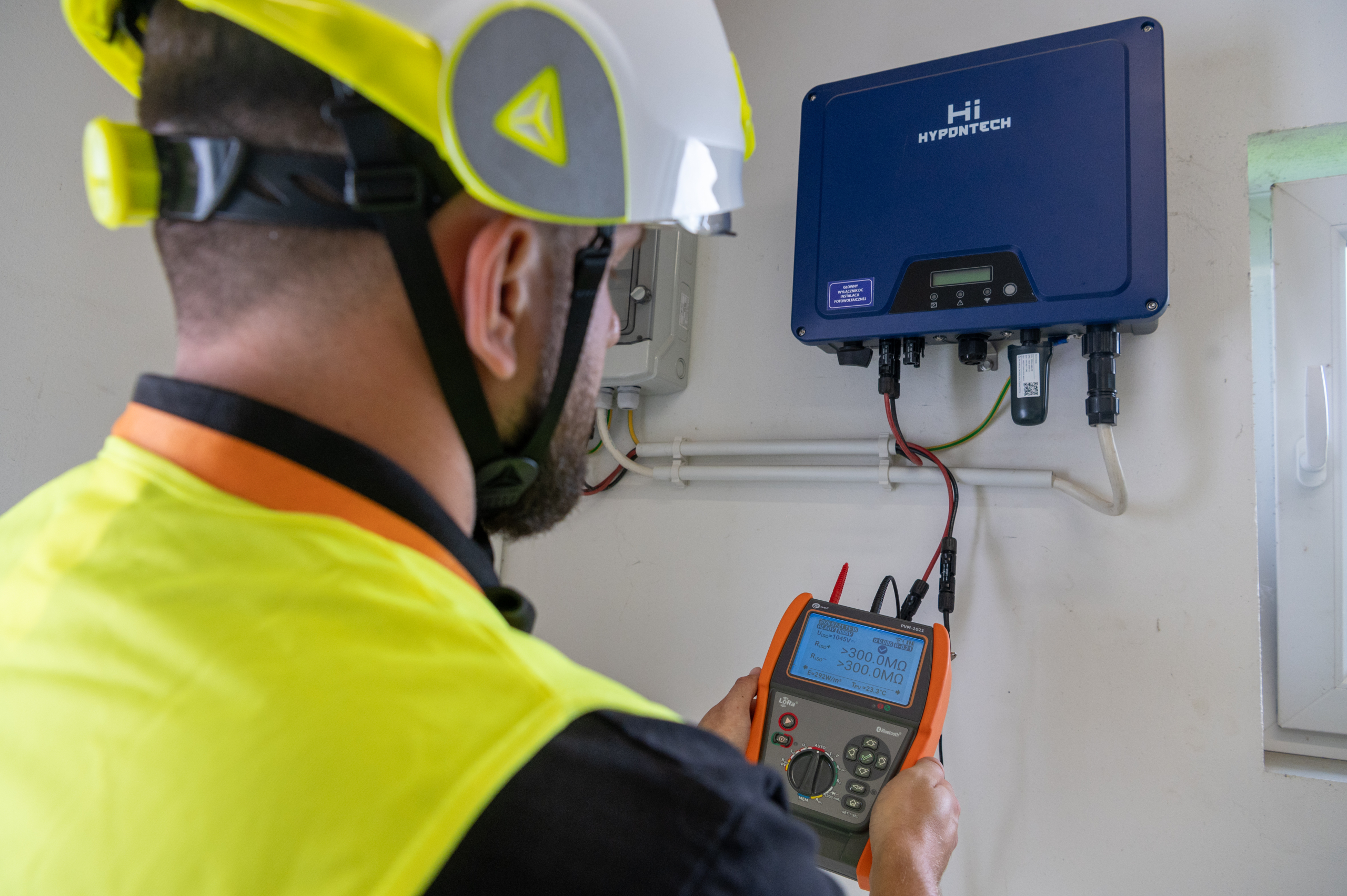
Sonel PVM-1021 – summary of measurements in automatic mode
Stage 5 – Thermal imaging inspection with Sonel KT-525-PRO camera
The final stage of an inspection can be made with a thermal imager, This inspection of the PV modules serves as an excellent addition to the basic range of electrical testing made with a PVM meter. The Sonel KT-525-PRO thermal imaging camera was used to evaluate the temperature distribution on the surface of the modules. The inspection enabled precise analysis of the thermal state of module surfaces and identification of any potential issues across the modules, connectors, and electrical connections.
Thermal diagnostics in photovoltaic installations enable a rapid detection of faults such as:
- Locally overheating cells
- Irregularities in the operation of individual module sections
- Unwanted activation of bypass diodes
- Overheating junction boxes and electrical connections
- Effects of soiling or partial shading of modules.
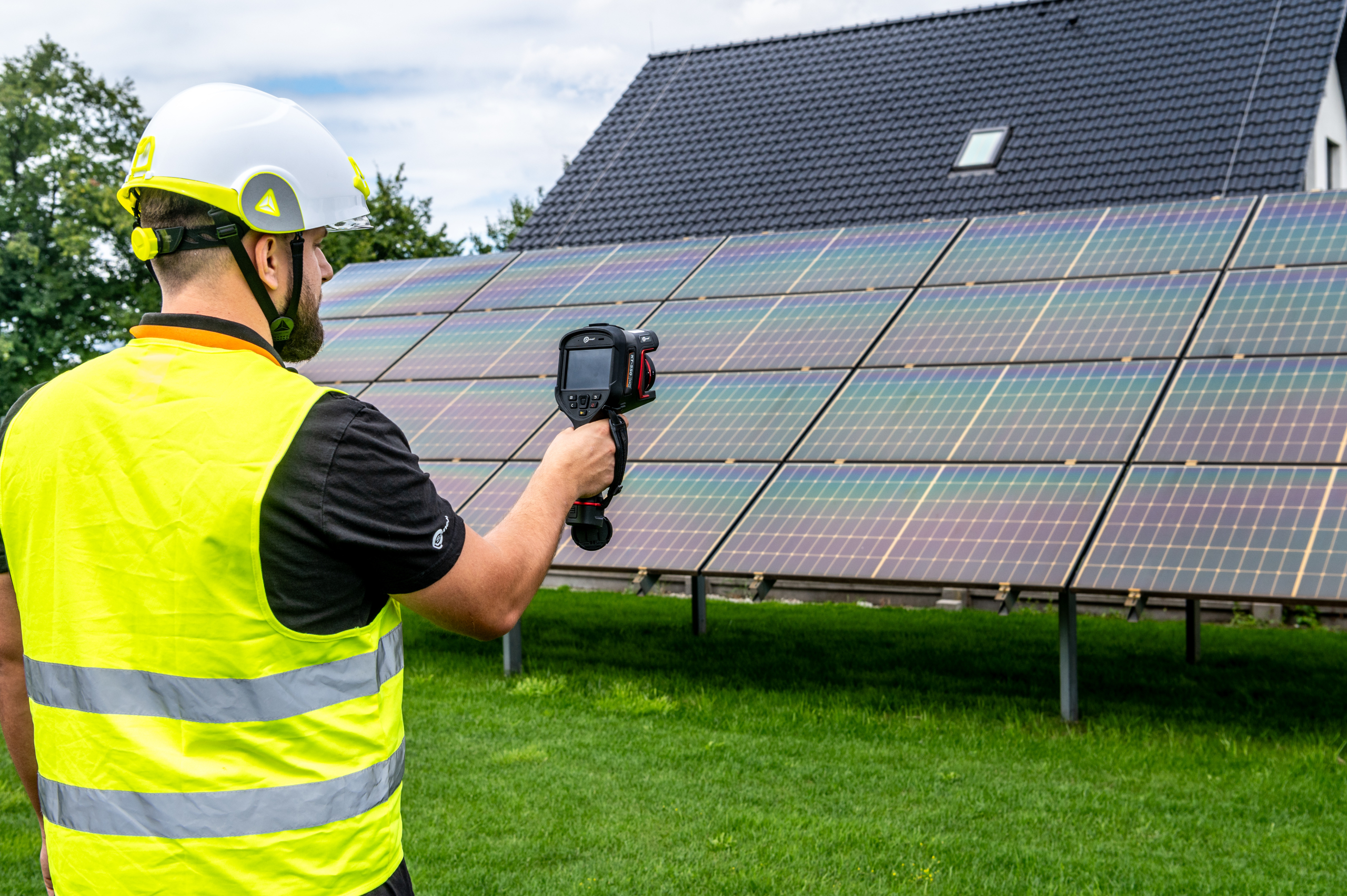
Additional electrical testing with thermal imaging inspection
Summary – Comprehensive diagnostics is more than just energy monitoring
Periodic inspection of an existing PV installation should include be for not only evaluating its current performance, but also for verifying the technical condition of any components that remain outside direct inverter control during normal operation.
Measuring the continuity of the protective conductors and the equipotential bonding, the open circuit voltage, short circuit current and the insulation resistance allows for the evaluation of these basic electrical parameters on the DC side and for detecting irregularities that do not always cause a noticeable drop in energy yield.
Complementing electrical measurements with visual inspection and thermal imaging can give a more complete picture of the installation condition. Thanks to this, the inspection is not limited solely to testing whether the installation produces energy, but also allows for the assessment of other areas that may requiring further diagnosis.
Learn more about our products and services by visiting our Power Quality Expert product catalogue, Sonel product catalogue , Electrex product catalogue or Elspec product catalogue or you can contact us to discuss your measurement requirements further.
You can also follow Power Quality Expert on LinkedIn for regular news on products, events and technical updates.