Description
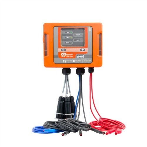
Sonel PQM-750 fixed permanent power quality meter
The Sonel PQM-750 is a permanent sub meter designed to measure and record power supply parameters for compliance with standards and applicable laws, and with the ability to verify preset terms of a DNO connection agreement.
Made in class A. Designed to be mounted on a DIN rail (with the possibility of mounting on a wall in a cabinet). The modular design allows adding new modules to expand the capabilities of the meter. The instrument allows measurements in 50 Hz, 60 Hz and 400 Hz networks.
Features
- Full class A according to IEC 61000-4-30, confirmed by a certificate from an accredited laboratory
- Voltage inputs L1, L2, L3, N, E (5 terminals)
- L1, L2, L3, N, E currents (5 current transformers)
- Built-in current transformers 5 A (optional: 1 A*), possibility of indirect measurements with calculation results for the primary side (optional: version with external current transformers*)
- Operation in 50 Hz, 60 Hz networks, operation in 400 Hz networks
- Recording of voltage and current events along with waveforms
- Measurement of more than 4,000 parameters
- 24-bit analog-to-digital converter
- Basic sampling rate of 80 kHz
- Conducted emissions monitoring in the 2…150 kHz band
- Two LAN ports, including one with the option of powering the meter with PoE (Power over Ethernet)
- Power supply 85…264 V AC (120…300 V DC), built-in rechargeable battery
- 8 GB memory (microSD card)
- USB port for meter updates and data exchange
- Two binary inputs, two relay outputs, two RS-485 ports
- Relay output to monitoring analyzer operation (Watchdog)
- 1-wire input for external temperature sensors
- 2.4” touch screen
- DIN rail or wall mounting
- Expansion bus allowing connection of various external modules (e.g. GPS, LTE)
- Built-in web server for programming the meter, reading current data, viewing the list of recorded events with oscillogram/RMS display
- Time synchronization with the reference via NTP servers, IRIG-B (via built-in RS-485)
- Optional GPS module
- Measurement category CAT III 600 V (IV 300 V) for voltage inputs
- Measurement category CAT III 300 V for current inputs
- Possibility of sealing current and voltage inputs
Additional features
- Standard transmission protocols
- Modbus TCP/IP
- Modbus RTU
- IEC 61850
- PQdif
- Web interface (webserver)
- Access to the interface from any web browser
Modularity
The instrument can be expanded with additional communication protocols and physical and software functionality.
Additional internal modules
- Transient module
- SSR relay module
- 18…60 V DC power supply unit
Additional external modules
- LTE GSM module
- GPS module with IRIG-B output
- I/O module
- LCD 7” touch panel for full operation of the analyzer at the mounting location
Measured parameters
Built-in software (web interface – webserver) allows you to configure the device and view actual data. It allows measurement of the following parameters.
- Phase RMS voltage U for L1, L2, L3+N/PE
- Phase-to-phase RMS voltages U for L12, L23, L31
- RMS currents I of all phases + N + PE
- Crest factor CF of voltages and currents
- Network frequency f for L1
- Active power P for L1, L2, L3
- Active power P1 (separated 50 Hz) for L1, L2, L3
- Reactive power Q for L1, L2, L3
- Reactive power Q1 (separated 50 Hz) for L1, L2, L3
- Apparent power S for L1, L2, L3
- Apparent power S1 (separated 50 Hz) for L1, L2, L3
- Three-phase total power P3F, Q3F, S3F
- Three-phase total power P13F, Q13F, S13F
- cosφ for L1, L2, L3, cosφ3F
- Power factor PF for L1, L2, L3, PF3F
- tgφ for L1, L2, L3, tgφ3F
- Distortion power D for L1, L2, L3
- Three-phase total distortion power D3F
- Distortion power factor DPF for L1, L2, L3
- Shape of phase voltages and currents for events
- Phase diagrams for currents and voltages
- Active energy for L1, L2, L3 – taken EP+ or given EP-
- Three-phase active energy – drawn EP3F+ or given EP3F-
- Inductive reactive energy for L1, L2, L3 for consumption – EQL+
- Capacitive reactive energy for L1, L2, L3 for consumption – EQC+
- Three-phase reactive energy for consumption – inductive EQL3F+ and capacitive EQC3F+
- Apparent energy for L1, L2, L3 – ES
- Three-phase apparent energy ES3F
- Harmonics hn to 256th in current and voltage
- Interharmonics up to 256th in current and voltage
- Angles between current and voltage harmonics
- Monitoring of 2…150 kHz bandwidth
- UDC phase voltage components
- Shares of harmonic currents and voltages in relation to RMS value (%) – hnR
- Shares of harmonic currents and voltages in relation to the fundamental harmonic h1 (%) – hnF
- THDR for voltages and currents calculated against RMS value (%)
- THDF for voltages and currents calculated relative to the fundamental harmonic (%)
- TIDR for voltages and currents calculated against RMS value (%)
- TIDF for voltages and currents calculated relative to the fundamental harmonic (%)
- Active and reactive harmonic powers
- K-factor for I1, I2, I3, IN
- Factor K (Europe)
- Symmetrical voltage components: zero U0, direct U1, inverse U2
- Voltage values (V, %) of harmonic components of the order compatible (1, 4, 7,…), opposite (2, 5, 8,…), zero (3, 6, 9,…)
- Symmetrical components of current: zero I0, direct I1, inverse I2
- Values of currents (A, %) of harmonic components of the order direct (1, 4, 7,…), inverse (2, 5, 8,…), zero (3, 6, 9,…)
- Short-term light flicker factor Pst
- Long-term light flicker factor Plt
- Voltage unbalance
- Current unbalance
- Transients U up to 6000 V
- Ripple control signals
- Temperatures: Tw (analyzer internals), Tz1…Tz4 (1-wire)
Standards
Made in class A of the IEC 61000-4-30 standard, the instrument is compliant:
Product standards
- IEC 62586-1 – Power quality measurement in power supply systems – Part 1: Power quality instruments (PQI)
- IEC 62586-2 – Power quality measurement in power supply systems – Part 2: Functional tests and uncertainty requirements
Standards for measuring network parameters
- IEC 61000-4-30 – Electromagnetic compatibility (EMC) – Testing and measurement techniques – Power quality measurement methods
- IEC 61000-4-7 – Electromagnetic compatibility (EMC) – Testing and Measurement Techniques – General Guide on Harmonics and Interharmonics Measurements and Instrumentation for Power Supply Systems and Equipment Connected thereto
- IEC 61000-4-15 – Electromagnetic compatibility (EMC) – Testing and Measurement Techniques – Flickermeter – Functional and Design Specifications
- EN 50160 – Voltage characteristics of electricity supplied by public electricity networks
Safety standards
- IEC 61010-1 – Safety requirements for electrical equipment for measurement control and laboratory use. Part 1: General requirements
- IEC 61010-2-030 – Safety requirements for electrical equipment for measurement, control, and laboratory use – Part 2-030: Particular requirements for equipment having testing or measuring circuits
Standards for electromagnetic compatibility
- EN 55032 – Electromagnetic compatibility of multimedia equipment – Emission Requirements
- IEC 61000-6-5 – Electromagnetic compatibility (EMC) – Part 6-5: Generic standards – Immunity for equipment used in power station and substation environment

The Sonel PQM-750 is an approved product on the Energy Technology List.
For more information visit the Sonel product page